yes, I know, I said I would post about the AV-bay next. Well, I stopped work on the AV bay, as I am rethinking my recovery plans, which has me rethinking my electronics decisions. I’m not changing my electronics choices, but I may use the third bay for a tracker instead of the Altus Metrum, then mount the Altus Metrum in the nosecone (which will be foamed), with another tracker.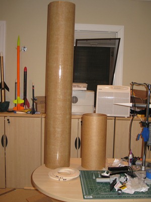 I’m thinking about separating the nosecone at main deployment to ensure it doesn’t do any damage to the airframe. I recently got the Scott Glass Olgive nosecone in (Thank you Scott Broderick!), and it is rigid, and heavy!
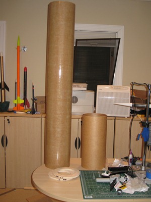
First, the coupler. Honestly, I thought this was going to be a cakewalk. do a little measuring, a little sanding, and a little gluing, and I’m done. All that was accurate, I just needed a little creativity to accomplish the task. The base kit calls for a 7.5” x 30” dynawind tube for upper airframe. I opted to increase the length to 48” originally, to give me the extra room I thought I needed to add my ele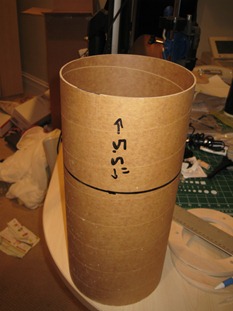 ctromagnetic deployment equipment. The extra length didn’t change any of the build plans for this portion. First up was to measure the coupler. 5.5” of the coupler is used to joining the two sections of the rocket, while the remaining space in the coupler will be housing the AV bay. I installed the coupler into the upper airframe up to the measurement point, then drew a complete line around the diameter of the coupler to indicate the section that would be left out, as well as drawing a line inside the airframe indicating where the coupler would end. I removed the coupler, then went about sanding both the outside of the coupler up to the line, and the inside of the airframe, down to the line. I shot a few lines of epoxy inside the airframe, a
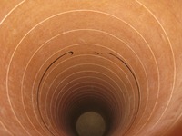 s well as on the outside of the coupler, then used a
 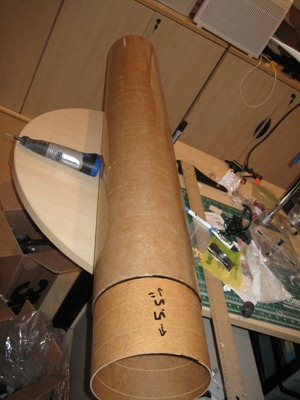 credit card to evenly coat both surfaces. So far, so good. Once again I clamped down the upper airframe and left everything to cure for the next 24 hours. I returned to a nicely epoxied coupler and re-measured everything to ensure nothing slipped overnight. The last step required was to install two centering rings into the airframe at the end of the coupler. The center rings each with 3 holes to allow the all thread of the AV bay to go through the center rings and get secured with wing nuts. This is a great design decision by Giant leap, as it *should* allow me to easily remove the AV bay for programming and prepping before a launch. When I went to install the couplers however, I cam to realize my arm won’t reach all the way through the upper airframe to both add glue, and position the two centering rings properly. The centering rings required fairly precise placement to ensure the all-thread holes were aligned properly. I couldn’t slide the center rings through the coupler end, as the
 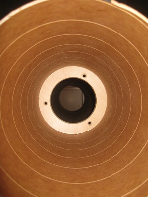 reduction in the inner diameter of the airframe was now sufficiently small to not let the center rings through. I then realized, even if I do figure this out (which I would), how in the world am I going to thread on the wing nuts onto the AV bay all thread when it comes time to install the AV bay? The solution to the second problem, turned out to be the solution to the first problem. I had NO interest in cutting a door on the rocket. Instead, I found a piece of spare PVC piping (I use it a lot to make rocket holders) cut it down to 18”, and used my dremel to cut out two ‘wingnut notches’ on either side of PVC wall. this will allow me to secure the wing nut into the PVC pipe, and use the PVC pipe as an elongated screw driver to install each of the wing nuts. I could also use the PVC pipe to push the center rings into place. the only real modification I had to do was CA the washers onto the forward facing center ring all thread holes – my little PVC trick won’t hold a washer correctly. Viola, mission accomplished. The only thing I don’t like about this solution is it now requires me to bring a custom build ‘tool’ to every launch I plan on flying this rocket. Time to add “Pack PVC wing nut driver” to my ever increasing pre-flight / pre-leaving home checklist. I waited another 24 hours, then did a trial run of installing the AV bay into the center rings. Bingo, they went right in, and my PVC pipe worked well as an elongated driver. Now that the upper airframe is complete, I can install it onto the lower airframe to add leverage to put the rocket on a stand, and start my external (and internal) fillets.
i don’t know how i got here, but this is cool. I was googling for Alex Zoghlin, that I used to work with at the National Center for Supercomputing Applications and founded Orbitz, and became a bazillionaire? Is this you ????
if so, what’s up! send me your contact info. What are you doing these days? I’m a team lead at facebook, working with a lot of people that used to work for you. I’m looking at getting back to the midwest.
if not, you still have a cool project dude. is there a link to someplace where i can get more info on this level 3 thing? can you buy a motor that big, or will you be building it?
Bazillionaire? heh. If that were the case, I would have a team of rocket scientists building my rocket.
Andrew, leave another comment with your email address. I’ll contact you offline and won’t post. I can probably get you back to the Chicago.