Fins… Fins… You’ve got to love fins.
In this case, I am using a material I’ve never used before. Both the fins and wings are made  from “fly-lite”. This is a Giant Leap brand aerospace composite material that consists of an inner layer of nomex honycomb, sandwiched between two thin layers of fiberglass. The end result is a very strong wing, that is about half the weight of g10, or wood. With my 3 large fins, and 2 large wings, I estimate I saved about 6 pounds off of the aft end of the rocket. Frankly, weight isn’t my primary concern, but stability is. Since I had already decided to foam the aft airframe, the weight savings here should keep the total weight of the rocket neutral, reducing the amount of nosecone weight I will need for
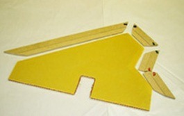 proper CG / CP. One of the issues you can clearly see wit this material is, it’s impossible to make a beveled leading edge with it. In my case I had custom MDF machined & mitered to cover all of the exposed edges. Just needed to bevel the MDF into a ‘tongue’, and use an exacto knife to build a ‘groove’ in the exposed edges. One REALLY nice things about the fly-lite material, is it is really easy to cut. In fact, I just drew around my template with a felt tip pen, and used a pair of shearing scissors to cut the line. You can’t
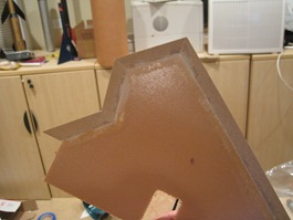 really get any easier than that! Of course, that means the perpendicular shear strength of the material is quite low. How low? well, the formula to compute shear strength is;
 While I don’t have the equipment to measure principal stress, I did use a piece to determine it’s ‘relative’ stre
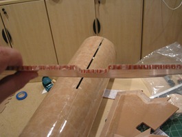 ngth. With the MDF epoxied in, there was no amount of stress parallel to the fiberglass sheeting I could create (using a complete set of weights) that would cause the material to fail. With perpendicular force however, it failed at about half the force of a duplicate sized piece of G10. My conclusion? Kevlar and fiberglass lamination.
With the fins cut, and the edging in place, it was now time to start epoxying the fins in place. I had already dry fit the fins and wings twice, so I was comfortable I wouldn’t have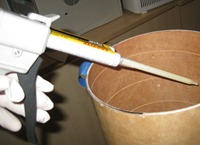 any fit issues. The only real complication was the upper fin tab would now be epoxied to the motor tube within an entirely closed portion of the airframe. I had already glued in place both center rings which would make it challenging to create inner fillets on the fin tab. My solution…. epoxy gun! for someone as messy as I, I tend to get epoxy in lot’s of places it should never be. I found glue guns (both large, and small) to be REALLY helpful when you need to get a bead of epoxy in a very
 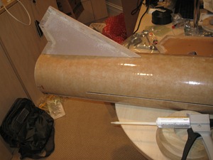 specific spot. They also have ‘mixing’ chambers within the tip, which mixes the two parts of epoxy as it exits the gun. This is VERY handy, although I have found it generally doesn’t mix epoxy nearly as well as doing it by hand in a measuring cup. In this case, I put a bead of epoxy on the fin tabs, then fit them into the through-the-wall fin slot. I left the fin on for a minute or so, then pulled it back out. Looking inside the upper fin tab slot, I could clearly see the line of excess epoxy left by the fin tab. I just inserted the epoxy tip through the slot, and put down a really nice bead of the high viscosity 120HP epoxy. I then reapplied another bead of expoy on the tab root, and the exposed lower centering ring, and reinserted the fin into the slot. I then put a little pressure tape across the outside edge of the fin to keep it in place, and clamped the airframe to my desk. peeking through the wing slots, I could cleary see a great motor tube / fin tab fillet had formed. The aft fin tab was open to viewing – it looked exactly like the upper tab without the big fillet, as I planned on making those later in the project, in conjuction with the outer fin fillets. turned out the lights, to let the epoxy cure for the next 24 hours.
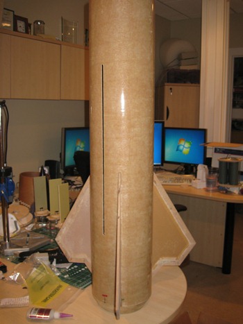
Over the next four days, I repeated this procedure for all three fins. I should mention I spent a fair amount of time ensuring the fins themselves were perfectly parallel to the airframe. While TTW slots make it much easier to get proper alignment, there is still a lot of ‘play’ through the slot. If they are not perfectly parallel, the rocket will tend to spin in flight. Not a big deal for a spectator, but I planned o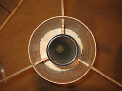 n adding video equipment in the rocket. There is nothing worse than watching a spinning rocket video – gives me a headache, and you really can’t see anything. Here’s a good example
I spent much of the time in between the fin epoxy curing building the AV-bay, which will be the subject of the next post. It’s one cool AV-bay.

Leave a comment